 |
||||||||||||||||||||||||||||||||||||||||||||||||||||||||||||||||||||||||||||||||||||||||||||||||||||||||||||||||||||||||||||||||||||||||||||||||||||||||||||||||||||||||||||||||||||||||||||||||||||||||||||||||||||||||||||||||||||||||||||||||||||||||||||||||||||||||||||||||||||||||||||||||||||||||||||||||||||||||||||||||||||||||||||||||||||||||||||||||||||||||||||||||||||||||||||||||||||||||||||||||||||||||||||||||||||||||||||||||||||||||||||||||||||||||||||||||||||||||||||||||||||||||||||||||||||||||||||||||||||||||||||||||||||||||||||||||||
|
The 1903 Smith & Wesson .32 Hand Ejector, Part 1: The No Change Model 1903 by Ed Buffaloe and Gaston Comeau
Introduction and Overview The .32 Hand Ejector was Smith & Wesson’s first revolver with a swing-out cylinder. It was manufactured in a number of variations from 1896 until 1942. Its history is the history of the development of the modern revolver. The .32 Hand Ejector was built on Smith & Wesson’s I frame, in the following variations, as defined by McHenry & Roper:
The period from 1903~1942, with which we are dealing in this article, was one of intense innovation at Smith & Wesson, as Daniel B. Wesson and his son Joseph H. (Joe) Wesson worked on perfecting the double action mechanism of their Hand Ejector revolvers. Some innovations appeared first, or concomitantly, in other Hand Ejector models chambered in .38 Special, .32 Winchester, or .44 Special, but in this article we are focusing only on the Model 1903 chambered in .32 Smith & Wesson Long. Information on variations and changes is taken primarily from McHenry & Roper’s Smith & Wesson Hand Guns and from Neal & Jinks’ Smith & Wesson, 1857-1945: A Handbook for Collectors; information on serial numbers is mostly taken from the latter, with minor changes that reflect our own observations. We gladly acknowledge our debt to the outstanding researchers who have preceded us. Additional information provided in this article is based on a critical examination of .32 Hand Ejector serial numbers 42, 7611, 13657, 25593, 37559, 45993, 54735, 90425, 95745, 98348, 101046, 224627, 262008, 314670, 378215, 398149, and 530711, as well as an examination of many photographs in the public domain. We welcome photographs and information about other Model 1903 Hand Ejector revolvers that might help improve the information in this article.* When patents are cited they will not necessarily be in the order of their invention or acceptance. The reader should bear in mind that for every generality there is usually an exception, and that manufacturing changes are not always implemented uniformly.
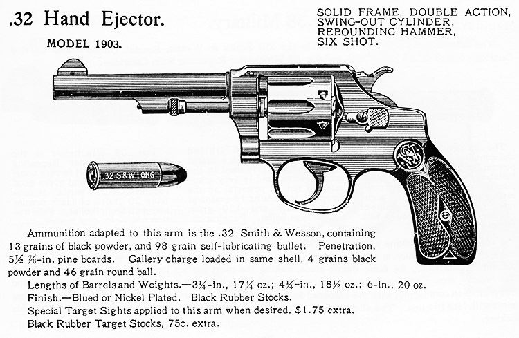
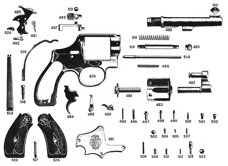
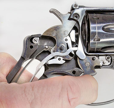
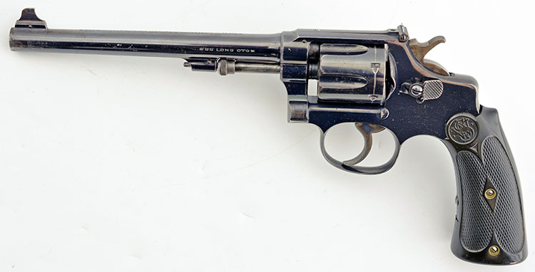
The Model 1903 was the Smith & Wesson company’s first .32 to look and function almost like its modern counterparts. Smith & Wesson Manufactured 19,425 of this No Change Model 1903 revolver over a two year period before they proceeded to make further innovations. Lockwork Two large flat springs are mounted in the grip frame. The rear spring is the mainspring (503) that tensions the hammer. The forward spring is the trigger spring (506) that tensions the trigger and operates the rebound mechanism.
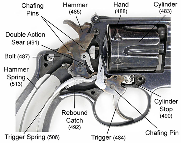
In the Second Model Hand Ejector, Model of 1903, the frame mounted rebound levers of the First Model Hand Ejector of 1896 are eliminated, replaced by a single seesaw lever that pivots on a pin fixed in the base of the hammer and which is referred to by Smith & Wesson as the “rebound catch” (492). This hammer-mounted rebound catch is tensioned by a small spring and plunger (511 and 505) in the lower portion of the hammer, forcing the front end of the catch down and the rear end up when the trigger is pulled to the rear.
The rebound catch acts to lock the hammer to prevent accidental firing. At rest, the rebound catch is aligned with the bottom of the frame, but if the hammer is pressed forward, the rebound catch locks against a stop in the frame, preventing further movement of the hammer. When the trigger is pulled to the rear, the trigger spring is lifted upward by the hand, allowing the rebound catch to rotate clear of the frame so the gun can be fired.
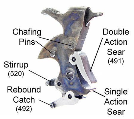
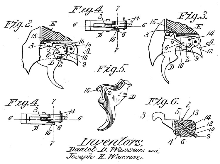
The hammer assembly includes the double action sear (491), the rebound catch (492), and the stirrup (520), all held in place by small pins. The solid chafing pins (U.S. Patent № 684331) and hammer nose (firing pin) pin are permanently installed.
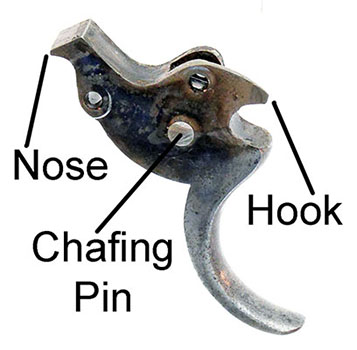
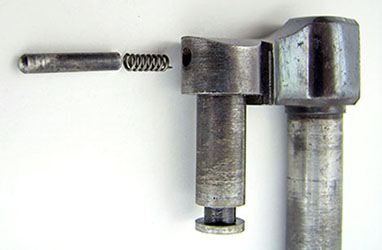
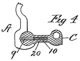
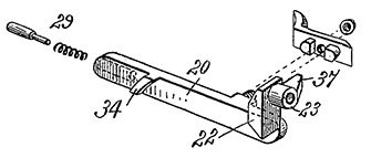
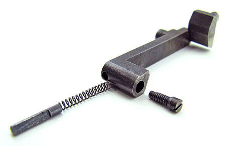
The cylinder stop (490) sits in front of the lockwork recess. Its purpose is to lock the cylinder in firing position. The cylinder stop turns on a stud screwed into the frame and is activated by the trigger hook which engages a pin on the side of the stop. The early cylinder stop, shown in U.S. patent number 611826, is tensioned by a small spring and plunger held in place by a pin through the body of the stop.
The cylinder stop (490) engages the cylinder notches through a slot cut in the bottom of the frame. When the trigger is pulled, the trigger hook leverages the stop out of engagement with the cylinder, while at the same time a pawl, known as the “hand” (488), attached to the rear of the trigger rotates the cylinder in a counterclockwise direction. The trigger nose engages the double action sear (491) to rotate the hammer backward. When the trigger gets to the end of its pull the nose slips free of the sear and releases the hammer to fall on the cartridge primer. The single-action sear is the small ledge beneath the toe of the hammer. This ledge catches on the nose of the trigger when the hammer is manually cocked.
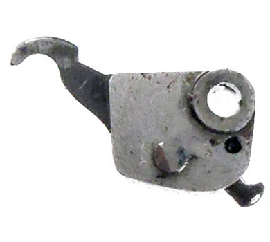
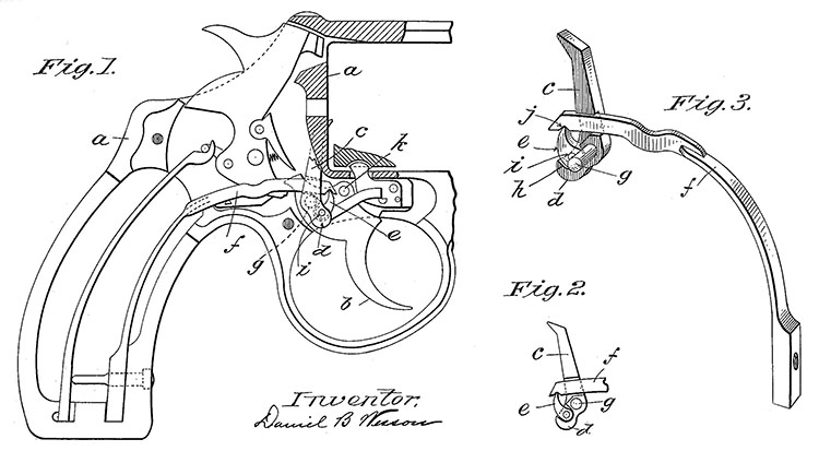
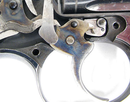
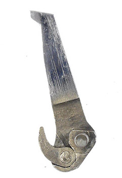
The hand (488) is tensioned by the trigger spring (506). The trigger spring presses downward on the hand to tension the trigger, but the hand needs to be tensioned in a more forward direction, so a tiny rotating lever is fitted to its back side. This lever engages with a notch near the end of the trigger spring, leveraging the hand forward.
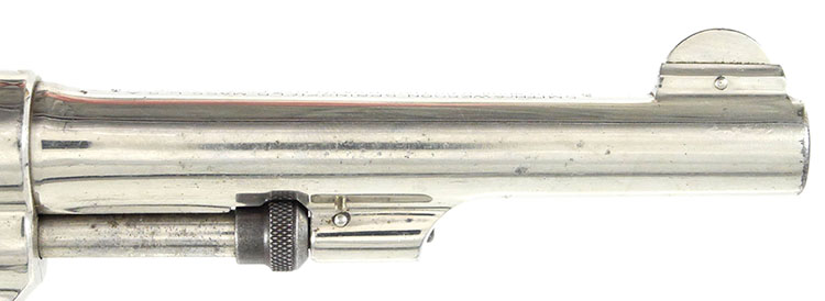
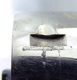
The hammer (485) and trigger (484) are case hardened whereas most of the other lockwork parts are unfinished bare metal, “in the white” in firearms terminology. The case hardened surface of the hammer is protected from scratching by patented chafing pins which extend a few thousandths of an inch beyond the sides of the hammer (see U.S. Patent № 684331). McHenry & Roper and Neal & Jinks report that a chafing pin was added to the trigger with the First Change variation, but we have found that all No Change Model 1903 triggers also have chafing pins. External sides of the trigger spring (506), cylinder release bolt (487), double action sear (491), hand (488), and cylinder stop (490) are polished to a mirror finish. This polishing is accomplished by a process known as glass-lapping: a piece of glass with one surface etched to a rough finish is coated with a polishing compound, such as tripoli or rouge, and the parts to be polished are rubbed on the coated surface until they take on a mirror finish. The glass-lap process was used into the 1940’s. In other S&W revolvers, the mainspring screw (518) is threaded into the front strap of the frame. However, in the early Model 1903 .32 Hand Ejector (No Change and First Change), the hole in the frame is not threaded. Instead, the hole in the trigger spring (506) is threaded to fit the strain screw. Barrel, Cylinder, and Yoke During the 19th century, most Smith & Wesson revolvers had a full length rib on top of the barrel, with the front sight pinned to that rib. The First Model .32 Hand Ejector (Model of 1896) retained this barrel rib; however, the rib is eliminated in the .32 Hand Ejector of 1903. The barrel tapers slightly toward the front, and the only remnant of the rib is a raised boss at the front to which the front sight is pinned. The barrel is screwed into the frame and pinned in place.
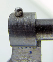
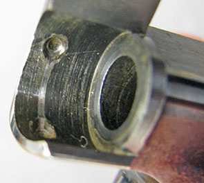
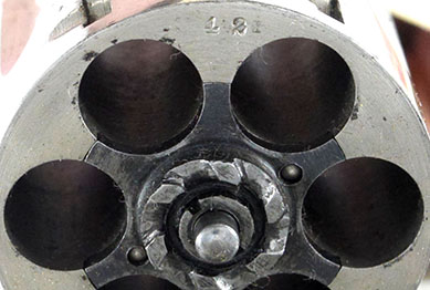
The Model 1903 .32 Hand Ejector cylinder locks at both ends of the center pin to assure proper alignment with the barrel. Perhaps the front lock for the cylinder was necessitated by the Wesson’s decision to rotate the cylinder counterclockwise, opposite the direction of yoke closure. Maybe the Wessons realized that when the cylinder rotates in the opposite direction of yoke closure the hand may push the cylinder out of alignment. However, the patent cites the possibility of a substance becoming lodged between yoke and frame, thus “springing the yoke”. In any case, the front lock prevents misalignment of the cylinder. U.S. patent № 689260 of December 1901 covers the front lock for the cylinder pin. An underlug on the barrel contains the spring loaded locking pin for the front of the cylinder ejector rod. The barrel underlug and sight boss are forged as part of the barrel. Late Model 1903 “No Change” guns have the front sight forged as part of the barrel as well, so the front sight does not require a pin. Like its predecessor (the First Model Hand Ejector of 1896) the cylinder stop notches of the Model 1903, have hardened steel shims to prevent the cylinder bolt from wallowing them out. At this time the steel used in the cylinders was relatively soft and the notches were subject to wear; such wear is often seen in earlier Smith & Wesson revolvers, as well as in some of the inferior Spanish revolvers of the early 20th century. The U.S. patent for the shims, № 401087, was granted in April of 1889. Even with the cheap labor of the era, shimming the cylinder notches was time consuming and contributed to the premium cost of the Smith & Wesson revolver.
Beginning with the First Model Hand Ejector of 1896, the cylinder yoke (482) of Smith & Wesson Hand Ejector revolvers is stabilized by a small spring and plunger (509 and 496), referred to as the yoke stop. There are detents in the frame into which the stop fits in both the open and closed positions (unlike the patent drawing, which shows a detent only for the open position).
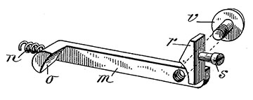
Cylinder Release or Cylinder Bolt Two safety cylinder release mechanisms were patented by Daniel B. Wesson, one in 1896 (see U.S. Patent № 573736) and another in 1899 (see U.S. Patent № 635705). They both consist of a spring loaded sliding bar that runs in a groove cut in the left wall of the frame, with a forward projection at the front and a lateral projection at the rear. The company has always referred to this bar as the “bolt” (487).
The two patents accomplish the same end using slightly different mechanisms, though neither works exactly like the mechanism as it was implemented in the Hand Ejector. The cylinder release, as we know it today, is derived from these two patent designs. In the mechanism, as implemented, cocking the hammer locks the bolt and the cylinder cannot be opened. With the hammer down, the bolt is not blocked, and pressing the release button forward will push the spring loaded center pin out of its recess in the recoil plate, allowing the cylinder and yoke assembly to be opened. With the cylinder open, the rear spring holds the bolt forward and the lateral projection at the rear of the bolt prevents the hammer from being cocked. The bolt spring (508) and plunger (500) are held in place by a set screw in the rear of the bolt which is not shown in either patent.
Sideplate and Fouling Cup
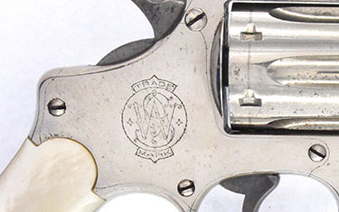
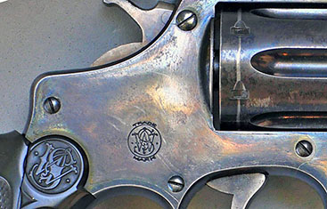
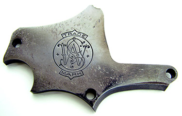
The sideplate (481) is secured by four screws. The top screw (503), beneath the hammer, is a short screw with a small shank diameter, fine threads, and a head larger than the others. The remaining sideplate screws (501) have a longer shaft. The yoke screw (502) is slightly shorter than the plate screws since its additional purpose is to hold the yoke in place, and it must not bind in the retaining groove. As on the Model 1896 Hand Ejector, the large size S&W monogram remains centered on the sideplate of early No Change revolvers. Sometime between serial numbers 13153 and 13350 we begin to see a smaller Smith & Wesson monogram centered near the bottom of the sideplate. The small monogram on the right sideplate is rarely, if ever, seen in later changes.
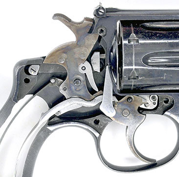
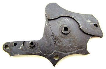
There are holes in back (inside) of the sideplate to accept studs for the cylinder stop, trigger, and hammer. The trigger and hammer holes have bosses, which hold their respective parts in proper alignment. The cylinder stop has an integral boss, as shown in the No Change lockwork detail photograph.
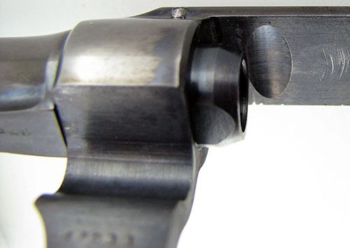
A feature rarely mentioned is the fouling cup, which is a relief cut in the underside of the topstrap just at the barrel and cylinder interface. This cut is a remnant from the days of black powder when only a few shots from black powder cartridges could foul a revolver action to the point where the cylinder would not turn. The fouling cup provides a little extra room for powder residue above the cylinder. Black powder cartridges were still available well into the 20th century so Smith & Wesson revolvers retained this feature until around 1920, though the use of black powder cartridges began to decline rapidly after 1907. Inscriptions and Stocks The left side of the barrel is marked in upper case sans serif characters: 32 LONG CTG The inscription, with patent dates, is on the top of the barrel. We cannot claim to list all inscriptions, but we list the ones we have observed. The number of lines in an inscription generally varies with barrel length. Inscriptions are bracketed by typographical dingbats, usually in the shape of a stylized cross. An early gun with 4¼ inch barrel (serial number 42) lacks the later patent dates, and has its inscription on three lines in all capital sans serif characters, as follows: SMITH&WESSON SPRINGFIELD MASS. U.S.A. A six inch length barrel inscription (serial number 7611) is on two lines in all capital sans serif characters, and includes the 1903 patent date, as follows: SMITH&WESSON SPRINGFIELD MASS.U.S.A.PAT’D APR 9.89.MAR 27.94.MAY
A slightly later example (serial number 9378) includes the 1902 patent date but not the 1903; its 3¼ inch barrel has an inscription on four lines in all capital sans serif characters, as follows: SMITH&WESSON SPRINGFIELD MASS. U.S.A. A still later example (serial number 16376) also includes the 1903 patent date: SMITH&WESSON SPRINGFIELD MASS. U.S.A. The Model 1903 continues to have the same standard stocks as the Model 1896, which are of checked hard rubber and feature the S&W monogram in a circle at the top. Since most stocks are hand fitted, the serial number is stamped on back of the right stock, or sometimes scratched or penciled, especially in the case of custom stocks. Target stocks are oversize square-butt, also made of checked hard rubber, with two grip screws—one in the middle and a longer one near the bottom. Target stocks did not usually require close fitment and so are rarely numbered to the gun. Premium factory stocks in mother of pearl and ivory were not always listed in the catalogs but were sometimes available by special order. Factory original premium stocks have gold plated brass Smith & Wesson monogram medallions inset near the top.
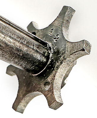
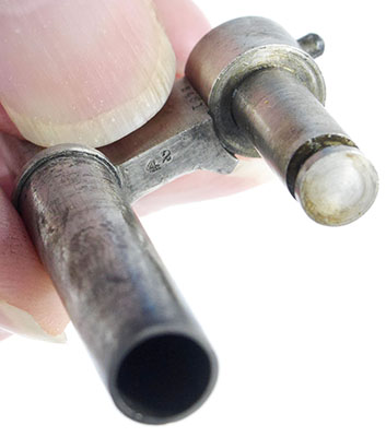
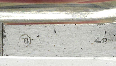
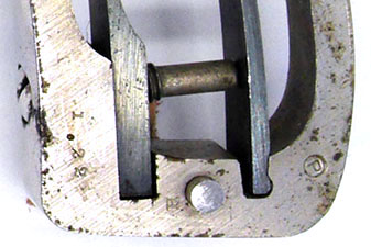
Serial Numbers, Fitting Numbers, Rework/Repair Stamps Assembly or “soft fitting” numbers may be found stamped in the yoke cut of the frame, on the yoke itself, and on the sideplate; these parts are machined together and are numbered so they will stay together through the rest of the production process. Stocks, barrel, and cylinder are all hand fitted to the frame and the serial number is stamped on the base of the grip frame, on the rear face of the cylinder, on the bottom of the barrel in the flat at the rear, on the back of the extractor, on the cross bar of the yoke, and behind the right stock. Target models may have the serial number stamped on the bottom of the rear sight, and partial serial numbers stamped on other small factory parts such as the front and rear sight blades. A star next to the serial number, or sometimes on the grip frame, indicates a factory refinish or repair. Numbers stamped on the grip frame, separated by a period, usually indicate the date of a refinish or repair. The letter “B” stamped on the barrel flat or yoke indicates an original blue finish. Lack of the “B” may indicate an original nickel finish, as does a stamped “N”. The “P” in a circle indicates that the gun was re-plated with nickel.
A Note on Fitment From the earliest days of their partnership, Horace Smith and Daniel Wesson emphasized quality and precision in manufacturing. Their products have always been known for being well made and
accurate. Aficionados of Smith & Wesson revolvers know well their close fitment and precision. Roy Jinks, in his History of Smith & Wesson, says of the Smith & Wesson Straight Line target pistol
that “because of the tight tolerances to which the pistol had been built, the hammer fall was sluggish if it was over-lubricated.” Our experience with Smith & Wesson revolvers, in general, is that excess
lubrication can slow the action and increase trigger pull. Only the thinnest film of a high quality lubricant is required. Part 2: Model 1903 First, Second, and Third Change Part 3: Model 1903 Fourth, Fifth, Sixth Change, and Regulation Police |
||||||||||||||||||||||||||||||||||||||||||||||||||||||||||||||||||||||||||||||||||||||||||||||||||||||||||||||||||||||||||||||||||||||||||||||||||||||||||||||||||||||||||||||||||||||||||||||||||||||||||||||||||||||||||||||||||||||||||||||||||||||||||||||||||||||||||||||||||||||||||||||||||||||||||||||||||||||||||||||||||||||||||||||||||||||||||||||||||||||||||||||||||||||||||||||||||||||||||||||||||||||||||||||||||||||||||||||||||||||||||||||||||||||||||||||||||||||||||||||||||||||||||||||||||||||||||||||||||||||||||||||||||||||||||||||||||
|
Copyright 2024 by Ed Buffaloe and Gaston Comeau. All rights reserved. |
||||||||||||||||||||||||||||||||||||||||||||||||||||||||||||||||||||||||||||||||||||||||||||||||||||||||||||||||||||||||||||||||||||||||||||||||||||||||||||||||||||||||||||||||||||||||||||||||||||||||||||||||||||||||||||||||||||||||||||||||||||||||||||||||||||||||||||||||||||||||||||||||||||||||||||||||||||||||||||||||||||||||||||||||||||||||||||||||||||||||||||||||||||||||||||||||||||||||||||||||||||||||||||||||||||||||||||||||||||||||||||||||||||||||||||||||||||||||||||||||||||||||||||||||||||||||||||||||||||||||||||||||||||||||||||||||||
|
|
||||||||||||||||||||||||||||||||||||||||||||||||||||||||||||||||||||||||||||||||||||||||||||||||||||||||||||||||||||||||||||||||||||||||||||||||||||||||||||||||||||||||||||||||||||||||||||||||||||||||||||||||||||||||||||||||||||||||||||||||||||||||||||||||||||||||||||||||||||||||||||||||||||||||||||||||||||||||||||||||||||||||||||||||||||||||||||||||||||||||||||||||||||||||||||||||||||||||||||||||||||||||||||||||||||||||||||||||||||||||||||||||||||||||||||||||||||||||||||||||||||||||||||||||||||||||||||||||||||||||||||||||||||||||||||||||||
