 |
|||||||||||||||||||||||||||||||||||||||||||||||||||||||||||||||||||||||||||||||||||||||||||||||||||||||||||||||||||||||||||||||||||||||||||||||||||||||||||||||||||||||||||||||||||||||||||||||||||||||||||||||||||||||||||||||||||||||||||||||||||||||||||||||
|
A Comparison of the 1910 and 1914 by Ed Buffaloe The 6.35mm Mauser Pocket Pistol first appeared in 1910. It was given a major update in 1914, and a minor update again in 1934. I don’t have a 1934 version of the 6.35mm Mauser Pocket Pistol, so this article will deal primarily with the 1910 and 1914 versions, though I will provide what information I can find about the 1934 as well. Early Development of the Pocket Pistol
Josef Nickl was a young German engineer who had taken a job with the Mauser company in 1904. Nickl envisioned producing a family of pistols all based on a single design which could be scaled up or down as necessary for any cartridge. His idea was to start with a gun chambered for the 9mm Parabellum cartridge, which had been developed for the Luger pistol in 1902 and which was adopted by the German Navy in 1904. From 1906 to 1908 Nickl worked on designs and prototypes for a delayed blowback 9mm pistol. However, the action he was working with, which had been originally designed for a long rifle receiver, didn’t function reliably when sized down to a pistol. Nickl abandoned the delayed blowback mechanism in favor of a straight blowback design, for which Mauser engineers produced several prototypes in 1909. The blowback design, which the Germans referred to as Massenverschluß, or “mass locking,” required a very heavy slide and a specially designed buffer spring to damp the recoil of the powerful 9mm Parabellum cartridge. But ultimately the cartridge proved to be too powerful for the gun. Nickl tried using the 7.63mm Mauser cartridge in the gun, but it was also too powerful for a straight blowback design. He then tried reducing the powder load in the cartridge, but recoil continued to be a problem, plus the German military wasn’t interested in yet another new cartridge. So Nickle decided to start at the other end of the scale and build a gun for the 6.35mm Browning cartridge, which by this time had already proved a remarkable success for FN and Colt’s.
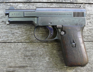
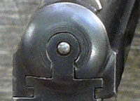
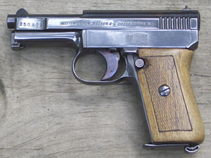
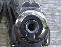
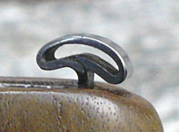
The 1910 Mauser is striker fired and has no hammer. The gun has an external extractor on the right side. The slide with integral breech block runs on rails in the frame which are offset to the right side of the gun. This gives the gun a slightly lopsided appearance, particularly when viewed from the rear. The slide is an open top design which leaves the barrel exposed. There are two arms on either side of the slide which extend beneath the barrel and meet in front to retain the recoil spring. The barrel has two perpendicular lugs that extend beneath it into the frame and are held in place by a long retaining pin which also serves as the recoil spring guide. The rectangular head of the retaining pin recesses into a notch on the underside of the barrel. The pin is spring loaded, so when it is pressed in the head can be rotated to allow the pin to be withdrawn from the gun. The gun has a conventional grip magazine that holds 9 rounds. The safety is a small lever behind the trigger which is pressed down to engage and has a button just beneath it to disengage. When engaged, the safety locks the sear lever and blocks the sear itself. The safety lever can also serve to lock the slide open when engaged. There is a cocking indicator on the back of the gun, and the frame is provided with wraparound grips, some of wood and some of hard rubber. Like the C96 Mauser “Broomhandle ,” the Mauser Pocket Pistols were made with no screws other than those that retain the grips. Serial numbers apparently began at 100, and are stamped on the left front portion of the slide and on the rear of the frame. The guns were left with a relatively flat luster and were rust blued with a bright fire blue trigger. In order to clearly delineate the differences between the 1910 and the 1914, I will list and describe each feature which was changed when the gun was updated. This is not an exhaustive list.
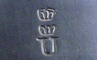
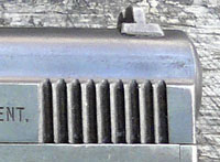
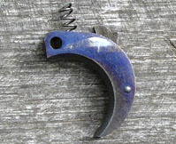
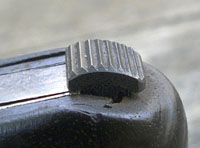
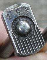
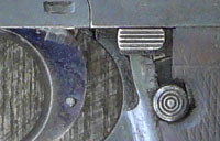
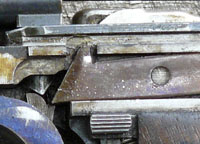
2. Right side slide legend. There is no legend on the right side of the 1910 slide. The forward portion of the slide bears the double crown over U proof of the Oberndorf proof house. 3. Serial number. The serial number is stamped on the left forward extension of the slide, as well as on the rear of the frame. The last two digits of the serial number are stamped on most parts that are large enough to accept them. 4. Frame. The frame is 4.9 inches long. The rear portion of the frame above the grip is squared off. There is sufficient room for a five-digit serial number. 5. Slide serrations. There are nine triangular-cut slide serrations. 6. Side plate and latch. The side plate has parallel sides with a step on the right side which fits into a slot in the frame. On its left side the plate is held in position by a combination latch and trigger pivot pin. When the latch is turned downward the pin can be removed. This frees the trigger and trigger spring and allows removal of the side plate. Replacing the trigger and spring in the correct orientation and inserting the pin can be tedious and usually takes me two or three tries--not something you want to do in the field, particularly since the trigger spring is small and easily lost. The Mauser logo appeared on most, but not all, of the side plates. 7. Trigger spring. The trigger spring was a small coil spring. 8. Cocking indicator. The cocking indicator consists of a separate spring-loaded pin positioned to the rear of the firing pin spring. When the action is not cocked the pin is flush with the rear of the gun. When the action is cocked the pin protrudes slightly from the rear of the gun. Visually, the two positions can be difficult to distinguish at a glance, but the pin is easily felt when it protrudes from the rear of the gun. This is only a cocking indicator and does not indicate that there is a round in the chamber. 9. Magazine. The magazine has a stamped sheet-metal follower and a pinned floorplate that sits flush with the bottom of the gun. Most magazines were nickle plated. 10. Magazine safety. There is no magazine safety mechanism--the gun can be fired without a magazine. 11. Magazine release. The magazine release is machined steel with transverse triangular-cut grooves. 12. Extractor. The extractor is 1.35 inches long and the rear .35 inches is narrower than the rest. 13. Ejector. There is no ejector on the Model 1910. 14. Slide hold-open mechanism. There is no mechanism on the Model 1910 to hold the slide open when the last round has been fired. The safety lever can be depressed to hold the slide open for disassembly. 15. Barrel retention pin. The head of the barrel retention pin has a rounded button in its center. The head extends upward and locks into a cut in the lower portion of the barrel. The upper portion of the head is stamped with the last three digits of the serial number. The lower portion has vertical triangular-cut serrations. There is a half-inch long coil spring on the end of the pin which tensions it so it cannot rotate out of the cut in the barrel. The pin also serves as the recoil spring guide. 16. Safety lever. The safety lever is about 0.3 inches long, very slightly rounded on its top surface, and has longitudinal v-shaped grooves cut into its surface. 17. Safety release button. The safety release is round, about 0.2 inches in diameter, and has circular grooves cut into it. It is slightly convex. A few of the earliest examples had checkered release buttons. 18. Disconnector. There is no true disconnector on the Model 1910. Rather, a projection on the forward portion of the sear lever moves into a hollow on the underside of the slide when the slide is forward, allowing the sear lever to move and release the striker. When the slide is not in its forward position, this projection butts against the base of the slide and prevents the sear lever from releasing the striker. Field Stripping the Model 1910
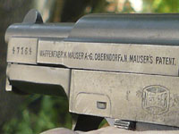
1. Left side slide legend. The words “Mauser’s Patent” were eliminated from the slide legend, and the font was changed to italic, so it read “WAFFENFABRIK MAUSER A.-G. OBERNDORF A. N. ” In 1922 the company changed its name to Mauser-Werke, but they apparently had a lot of slides already made, because the name change was not reflected on the gun until approximately 1929 (at about serial number 360,000), after which the slide
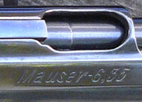
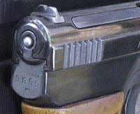
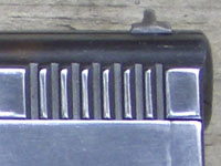
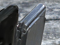
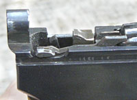
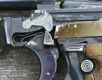
2. Right side slide legend. The right side was given the following legend in large italics: “Mauser-6,35”. 3. Serial number. The serial numbers remained in the same locations, but when they reached six digits only the last four were used on the rear of the frame. The rear of the frame was also stamped with a tiny intertwined WM logo. 4. Frame. The frame is 5 inches long. The new frame had to be lengthened by 0.1 inches to allow room for the slide lock mechanism. The rear portion of the new frame slants upward from the grip, whereas the 1910 frame was squared off at the rear. 5. Slide serrations. There are seven square cut slide serrations. 6. Side plate. The latch was eliminated from the side plate, so that it was no longer necessary to remove the trigger when the side plate was removed. The side plate has a step on either end, and the two ends are assymetrical, the right side being curved at the bottom. When the slide is removed, the sideplate can be pushed upward on the right side to remove it. 7. Trigger spring. The trigger spring is a flat spring. 8. Cocking indicator. The cocking indicator is a rearward projection of the firing pin which cannot be seen at all when the action is not cocked. This provides a clear visual indicator that the gun is or is not cocked, and eliminates two unnecessary parts. 9. Magazine. The magazine has a machined steel follower that serves to lock the slide open when the magazine is empty. The base plate is oversized and does not recess into the base of the grip. The magazines were blued rather than nickeled. 10. Magazine safety. When the magazine is removed the ejector (see below) is tipped forward and a projection on its rear blocks the sear, serving as a magazine safety. 11. Magazine release. The magazine release is a single stamped piece of steel with a return bend in the bottom which is tempered to make it a spring. The upper portion of this spring tensions the ejector/hold-open catch. 12. Extractor. The extractor is 1.68 inches long and uniform in width. 13. Ejector. The ejector is integral with the mechanism that holds the slide open, and is very unusual in that it is located on the right side of the magazine. The mechanism is spring-loaded to tip the ejector down and out of play until the magazine is inserted. The right lip of the magazine pushes the ejector up into position. 14. Slide hold-open mechanism. When the last round is fired and the magazine is empty the heavy steel magazine follower rises up and blocks the path of the returning slide, locking it open. When the magazine is withdrawn the rear of the spring-loaded hold-open catch is tipped upward to lock the slide open (however, if the spring is weak or has lost its temper, the slide may close). When the loaded magazine is reinserted, the depressed follower cannot hold the slide open, and the right lip of the magazine pushes the extractor up, tips the rear of the hold-open catch down, and releases the slide to chamber a new round. 15. Barrel retention pin. The head of the barrel retention pin has a smaller rounded button in its center and does not extend upward beneath the barrel. Instead, its lower portion curves around a lip beneath the front portion of the frame, where is is held in place by a flat spring clip. The head is smooth and no longer displays part of the serial number. The recoil spring has a separate guide with a hole through it, and the barrel retention pin is inserted through the center of the guide. 16. Safety lever. The safety lever is approximately 0.4 inches wide, and slopes outward to provide a better surface for the thumb to operate it. It narrows toward the front and has longitudinal v-shaped grooves which extend outward like small steps. 17. Safety release button. The safety release is nearly identical with the old one, except it is flat instead of convex. 18. Disconnector. The disconnector, located just above the trigger, rises up into a hollow on the underside of the slide when the slide is forward. When the slide moves out of this position , the disconnector is forced downward and prevents the trigger from engaging the sear lever. Field Stripping the Model 1914
The Model 1934 Changes to the 1934 model were relatively minor. The base of the magazine was simplified and the magazine catch was reformed slightly. Stewart says the 1934 was not as well machined as the 1910, but was polished to a high luster and salt blued. The triggers, extractors, and barrel retention pins were given a bright fire blue. The most visible change to the gun was that the shape of the grip was modified--the lower portion swelled out to make it more ergonomic. W.H.B. Smith claimed that variable grip shapes were available to suit the hands of individual shooters, but I have not found another source that backs this up, nor have I examined enough 1934 models to be able to verify it. The right side slide legend was changed to read “Mauser-6,35-D.R.P.u.A.P.”. The pistol was referred to by Mauser as the “M1934 Neues Modell”, and today is known as the 1910/34 or sometimes the 1914/34. Field stripping is the same as for the Model 1914. Parts List for the 1910 Mauser 6.35mm |
|||||||||||||||||||||||||||||||||||||||||||||||||||||||||||||||||||||||||||||||||||||||||||||||||||||||||||||||||||||||||||||||||||||||||||||||||||||||||||||||||||||||||||||||||||||||||||||||||||||||||||||||||||||||||||||||||||||||||||||||||||||||||||||||
|
Copyright 2009 by Ed Buffaloe. All rights reserved. |
|||||||||||||||||||||||||||||||||||||||||||||||||||||||||||||||||||||||||||||||||||||||||||||||||||||||||||||||||||||||||||||||||||||||||||||||||||||||||||||||||||||||||||||||||||||||||||||||||||||||||||||||||||||||||||||||||||||||||||||||||||||||||||||||
|
|||||||||||||||||||||||||||||||||||||||||||||||||||||||||||||||||||||||||||||||||||||||||||||||||||||||||||||||||||||||||||||||||||||||||||||||||||||||||||||||||||||||||||||||||||||||||||||||||||||||||||||||||||||||||||||||||||||||||||||||||||||||||||||||
|
|
|||||||||||||||||||||||||||||||||||||||||||||||||||||||||||||||||||||||||||||||||||||||||||||||||||||||||||||||||||||||||||||||||||||||||||||||||||||||||||||||||||||||||||||||||||||||||||||||||||||||||||||||||||||||||||||||||||||||||||||||||||||||||||||||
